Sky Charts
Encoder telescope plugin
This plugin can be used with an encoder box using Tangent
protocols like the Ouranos , AAM or NGC-MAX.
It uses a floating two stars alignment method based on an
article by Toshimi Taki in February 1989 S&T.
Please refer to the manufacturer information to connect the
telescope to the computer and to power.
Then use the main menu Telescope to select the encoder plugin
and start the interface. If you are asked to change the program
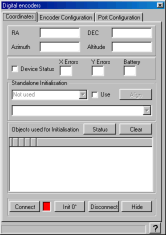
time to auto-refresh reply Yes. The following window is
displayed:

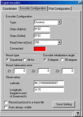
The first time you use this feature, you need to provide some configuration information.
Click the "Connect button", the light must change to green and the encoder count is displayed at the top of the screen.
Perform the following alignment procedure:
- If you select 90 degree initialization:
- point the telescope vertically for an altaz mount or parallel to the polar axis for an equatorial mount. It is important to understand that you must not point to the real zenith or pole but to the direction of your mount axis. Use of a fixed graduated circle or a stop piece can be of great help; see also the discussion about the Z3 parameter below.
- Click the "Init 90°" button.
- If you select 0 degree initialization:
- point the telescope horizontally for an altaz mount or perpendicular to the polar axis for an equatorial mount. The above note also applies in this case.
- Click the "Init 0°" button.
- Point the telescope to a star, use a reticle eyepiece and enough power to precisely center the star.
- Click the star on the chart.
- Select "Sync current object" from the "Telescope" menu or the right mouse button menu.
- Repeat the procedure for a second star. Be sure to choose a star with enough difference from the axis of the first star.
The position of the telescope is now displayed using equatorial and azimuthal coordinates.
You can now close the interface window by clicking the "Hide"
button.
Refer to the main menu Telescope help to learn how to display
the telescope position on the chart.
Remember you can refine the local precision by using "Sync
current object" on a nearby star at any time. You are not limited
in the number of initialization stars you choose.
The couple of stars used for the part of the sky the telescope
is actually pointed at are marked by a '*'.
The Clear button deletes all the stars in the initialization
list and returns the interface to the uninitialized mode.
A right mouse click on the list allows the deletion of one star
from the list.
If your interface returns status information, this is indicated just below the coordinates.
You can also do the initialization without the chart by using a star list, though this is probably less convenient. If you prefer to do so, check the "Use" box and select the star from the list. When this star is centered in the telescope click the Align button.
Main causes of errors
Sometimes the position shown on the chart is not the one you observe in the telescope. There are many causes of possible error - here is a short list:
- Configuration error:
- Number of encoder steps incorrectly set, principally if you gear the encoder. Use a full mount rotation with a fixed remote reference to count the exact number.
- Mount fabrication error not set.
- Mismatch between azimuthal and equatorial mount.
- The precision for two star alignment is dependent on a precise first direction initialization, use the Z3 parameter to correct a systematic error. There is, however, no need for a precise polar alignment or mount leveling.
- Unadapted reference stars, the first two alignment stars must have enough difference along the two axes and be far enough in the sky.
- Also avoid selecting an alignment star near the direction of the polar axis; Polaris is good for an azimuthal mount but not for an equatorial mount.
- Missing encoder count in the interface box, this may occur if you move the mount too rapidly or if the battery is low.
- Misidentification of a reference star.

Select the encoder type you use. If your model is not listed
consult your documentation to find a compatible model, if you
find none select the generic Tangent model.
Set the encoder count for a full rotation for both axes.
The read interval is the amount of time that elapses between two
position queries to the interface box. Use a smaller value for a
smoother cursor movement if your box accepts that and if your
computer as enough power. Use a larger value to use less computer
resource or if your interface box has a limited output rate.
Check the mount type (equatorial or Alt-Az) you use and if you
prefer to do the first initialization vertically or
horizontally.
The mount fabrication error angle Z1, Z2, Z3
in degrees are the ones defined in Taki article:
Z1 is the amount by which the elevation axis is offset from the
perpendicular to the horizontal axis.
Z2 is the pointing error of the telescope optical axis in the
same plane.
Z3 can be considered a correction to the zero setting of the
elevation circle.
Measuring Z1 and Z2 can be a difficult task, but Z3 can be of
great value in initializing the mount.
For example, imagine your Dobson mount as a security stop 5
degrees above the horizon to avoid flipping the primary mirror.
You can set Z3=5 and check the initialization at 0 degrees. To
initialize the mount simply point the telescope tube horizontally
to the security stop and click the "Init 0°" button, that's
all.
You can imagine the same if the stop is 15 degrees after the
zenith but in this case use the "Init 90°" button.
You don't need to set the observatory coordinates as this is automatically done from the location defined in Cartes du Ciel.
If there is a problem with the interface you can trace the protocol to a file by checking "Record protocol to a trace file".
The last check box lets you choose if you want this window always visible at the top of the other.
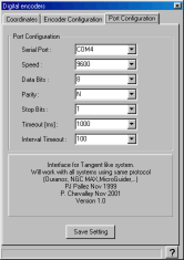
Communication port configuration

Select the serial port (COM1 to COM8) where the telescope is
connected.
Set other options (speed, data, parity and stop) according to
the manufacturer's information.
Change the timeout values only if you encounter communication
problems and after identifying the problem with the trace file.
Do not set the timeout to a value greater than the refresh rate
in the preceding screen.
Click the Save Setting button to keep your configuration for
the next run.
Also save the default options in Cartes du Ciel menu to keep
your interface choice.