FUNcube-1 AO-73 Satellite
Date: 20150104 1809UT
Summary
- YouTube Satellite FUNcube-1 AO-73 with Airspy SDR Time Lapse.
- Satellite:
FUNcube-1 AO-73
- Date: 20150104 1809UTC
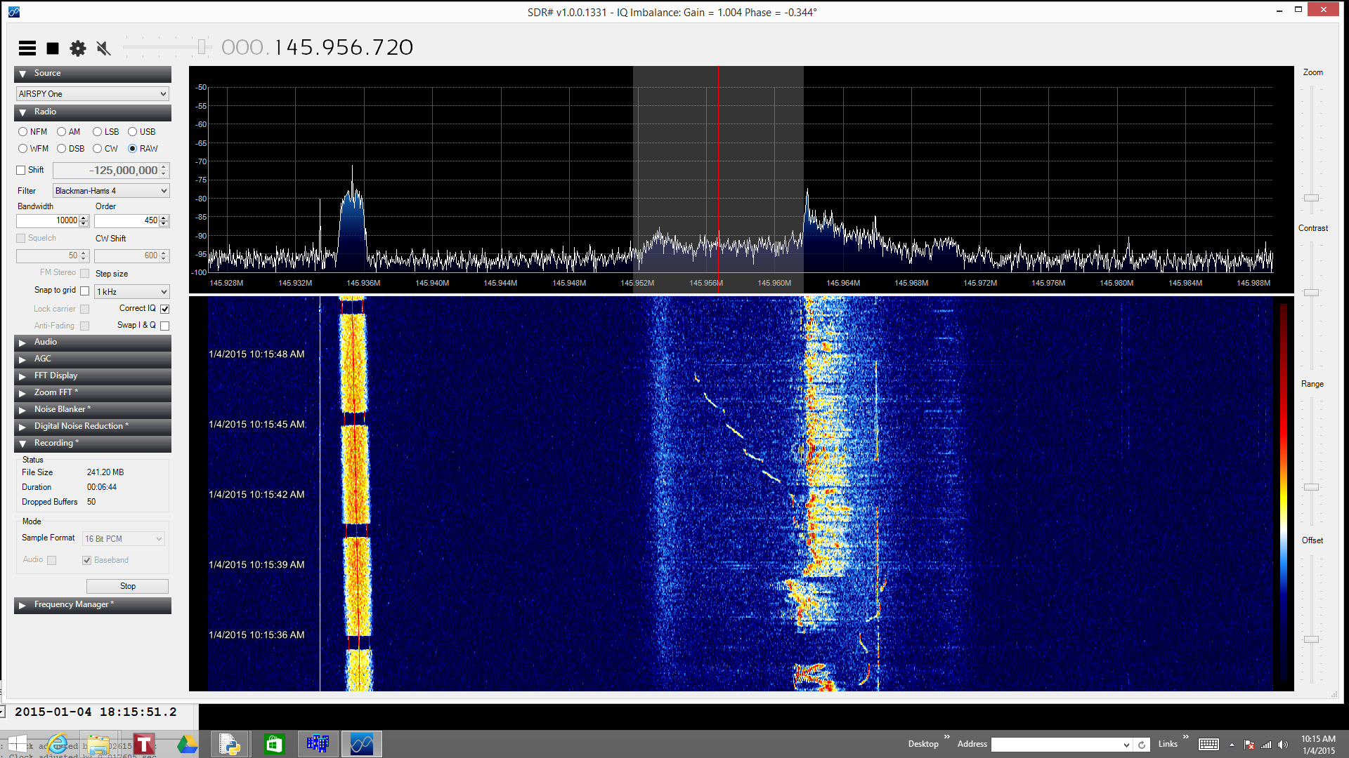
- Universal Time (UTC) in shown in the bottom left corner of the screen capture.
- Local time (PST) is shown in the spectrogram window on the left side.
- Spectrogram (also called water fall plot) shows frequency on the horizontal axis, time on the vertical axis, and signal intensity in color change.
- Spectrogram dark color is low signal intensity and red color is high signal intensity.
- Spectrogram current time is at the top of the window.
- Oldest spectrogram time is at the bottom of the window.
- TLM down link frequency: 145.935 MHz BPSK (+/- Doppler).
- Slanted colorful band on the left side to of the spectrogram.
- Transponder downlink frequency: 145.950 - 145.970 MHz USB (+/- Doppler) Mostly USB signals with some CW signals.
- Signals are from the center to half way to the right edge of the spectrogram.
- At ~ 18:15:15.6UT you can see the complete transponder band signal as a rise in the back ground noise.
- TLM beacon frequency Doppler shift is seen as a lower frequency shift through out the time lapse.
- Thin solid vertical lines in the spectrogram are local RFI.
- Notice the change in the RFI when the antennas are switched (~time 18:15:05 UT) .
- Occasional horizontal lines are strong local 2 meter signal over loading the preamp or RFI.
- Example of deep signal fading is seen at 18:15:34 UTC.
- The Airspy baseband IQ data was saved.
- The next step is to replay the baseband IQ data and decode the USB and CW signals recorded.
- Future areas of improvement is to manually track the satellite with the antenna.

Receiver
Antennas
- Two four elements Yagi Arrow II Portable Antenna Model 146-4 II are used.
- The antennas are positioned in the
azimuth
and
altitude
directions to see the satellite at certain positions in the sky.
- The second four element Yagi antenna has its own coax to the receiver.
- A coax switch selects which antenna to use.
- Also, the coax switch has three positions, two for the two different antennas
and one position to a 50 ohm terminator.
- The 50 ohm terminator provides a quick check on which signals are internally generated
from the receiving system and which signals are received from the antenna system.
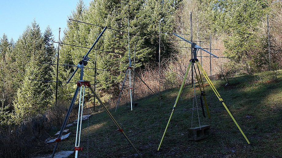
-
The above photo shows one four element Yagi antenna positioned east at 30 degrees altitude and
the second four element Yagi antenna positioned west at 30 degrees altitude.
- This configuration is used for casual monitoring (lazy mode monitoring) of the satellites.
- For this satellite pass,
- The first four element Yagi is aimed at 45 degrees azimuth and 35 degrees altitude.
- The second four element Yagi is aimed at 135 degrees azimuth and 45 degrees altitude.
- The two fixed positioned 4 element Yagi antennas are switched at satellite midpoint (~time 18:15:05 UT) across the sky.

Computer
- Laptop
- Toshiba Satellite P75-A
- Intel Core i7-4700MQ CPU @ 2.40 GHz
- 8 G RAM
- Microsoft Windows 8.1, 64-bit
- Data logging to Toshiba 2TB USB hard drive
Software
Satellite Tracking Software
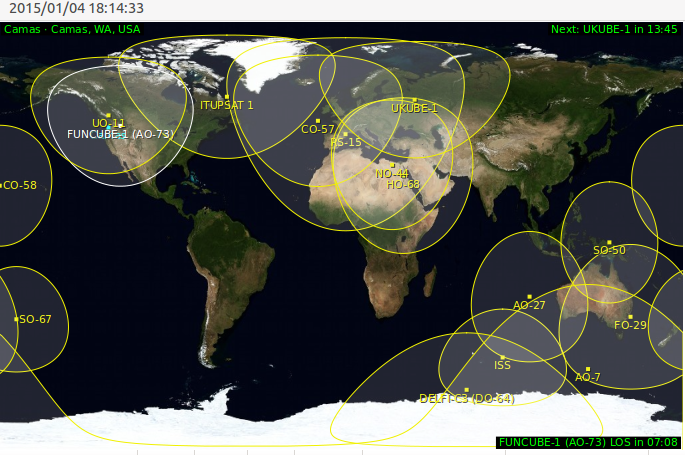
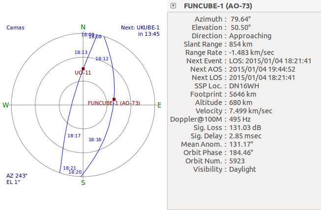
- GPREDICT 1.3 on Ubuntu 14.04 running on a MacBook Pro OS X 10.10.1 with Parallels Desktop 10.1.2.
Observation Location

© 1998-2015 David Haworth, WA9ONY
![]()
![]()


